The unit consists primarily of heat transfer plates, spacer columns, a central partition, end plates, and other components. The spacing between the heat transfer plates forms independent spiral channels. The two fluids flow in a fully counter-current manner along the spiral channels on either side, resulting in high heat transfer efficiency and full utilization of low-temperature heat sources.

Maximum Heat Transfer Efficiency

Compact and Lightweight Design

Low Fluid Resistance

High-Efficiency Utilization of Low-Temperature Heat Sources

High Adaptability
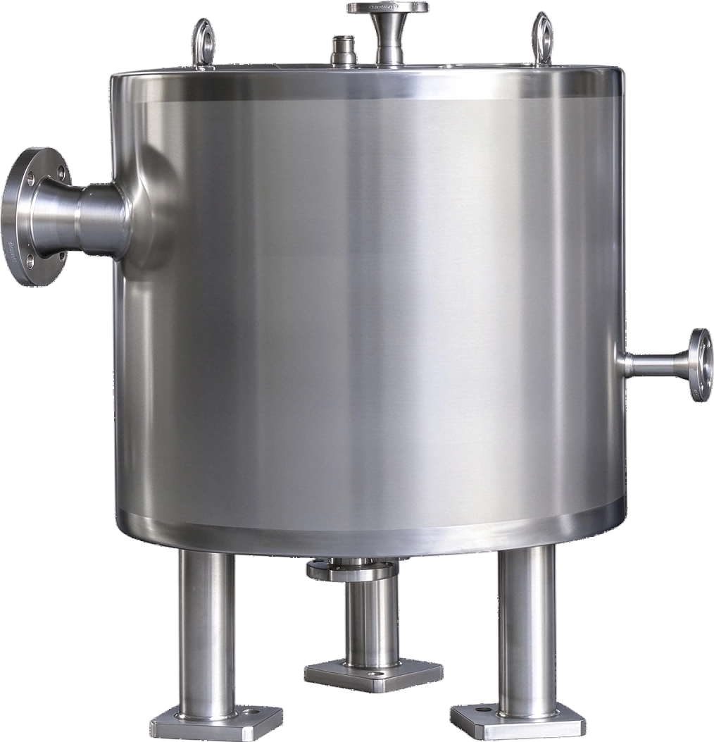

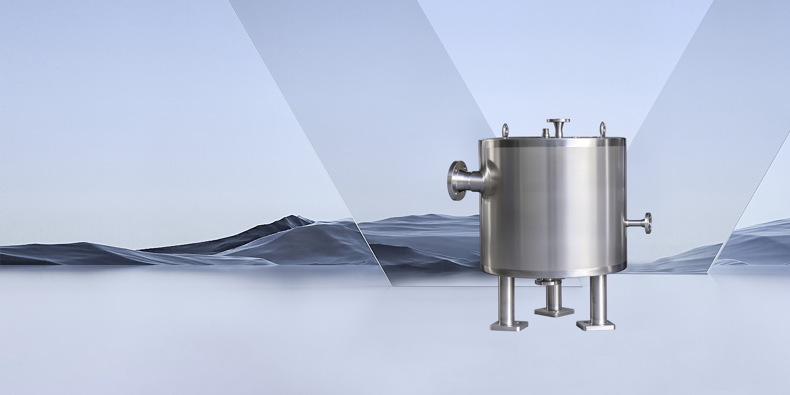
The Spiral Plate Heat Exchanger is a highly efficient, compact heat exchange device. With its compact design, low fluid resistance, and high adaptability, it is widely used in industries such as pharmaceuticals, chemical engineering, fine chemicals, food and oils, and environmental protection.
To facilitate heat exchange (heating or cooling) between two fluids
Multiple units can be connected in series or in parallel to accommodate larger heat transfer areas or special processes.
In industries such as pharmaceuticals, chemicals, and food processing, these systems are used for heating and cooling pharmaceutical solutions, maintaining a constant temperature in fermentation tanks, condensing solvent vapors, heat exchange involving highly corrosive media, temperature control of polymer resins, heating acidic and alkaline solutions, recovering waste heat from industrial wastewater, and controlling the temperature of flocculation reactions in wastewater treatment.

Chemical Industry

Pharmaceutical Industry

Food Industry

Environmental Protection Industry

Two separate spiral flow channels are formed by the heat transfer plate, through which fluids A and B flow, respectively. Spacer columns are welded to the heat transfer plate to ensure a constant channel spacing and to enhance turbulence. A central partition separates the inlet and outlet of the two fluids, enabling countercurrent flow.
The inlet and outlet ports are designed to be tangential to minimize fluid resistance.

Custom Materials

Surface Finishes

Structural Combinations
| Heat Transfer Area (m²) | Channel Spacing (mm) | Coil Plate Thickness (mm) | Material Inlet & Outlet | Cooling Water Inlet & Outlet |
|---|---|---|---|---|
| 2 | 10 / 12 | 2 / 2.5 / 3 | DN25 | DN25 |
| 3 | 10 / 12 / 19 | 2 / 2.5 / 3 | — | — |
| 4 | 10 / 12 | 2 / 2.5 / 3 | DN25 | DN25 |
| 5 | 10 / 12 | 2 / 2.5 / 5 | DN40 | DN25 |
| 6 | 10 / 12 | 2 / 2.5 / 5 | DN40 | DN40 |
| 8 | 10 / 12 | 2 / 2.5 / 5 | DN40 | DN40 |
| 10 | 10 / 12 | 2 / 2.5 / 5 | DN50 | DN40 / DN50 |
| 12 | 10 / 12 | 2 / 2.5 / 5 | DN50 | DN40 / DN50 |
| 15 | 10 / 12 | 2 / 2.5 / 5 | DN50 | DN40 / DN150 |
| 20 | 10 / 12 | 2 / 2.5 / 5 | DN50 / DN80 | DN50 / DN80 |
| 25 | 10 / 12 | 2 / 2.5 / 5 | DN50 / DN80 | DN60 / DN100 |
| 30 | 10 / 12 | 2 / 2.5 / 5 | DN80 / DN100 | DN80 / DN100 |
| 40 | 10 / 12 | 2 / 2.5 / 5 | DN80 / DN100 | DN60 / DN100 |
| 50 | 10 / 12 | 2 / 2.5 / 5 | DN100 / DN125 | DN100 / DN125 |
Note: Custom design and manufacturing are available to meet special user requirements, including material, structure, specifications and dimensions.


